
A television backlight is one of the most important components in an LCD/LED television display system. Its primary function is to provide the light that passes through the LCD panel and allows the television image to become visible.
Many people refer to modern LCD televisions simply as “LED TVs.” Technically, the LCD panel creates and controls the image while LED light sources provide the illumination behind or around the panel. The combination allows the television to display moving images, colours, text, menus and graphics.
Understanding the backlight is particularly important when diagnosing a television that has sound but no visible picture, a screen that is unusually dark, uneven illumination, flashing brightness, or a television that repeatedly starts and shuts down its illumination system.
A television can have a perfectly functioning mainboard, T-CON circuit and LCD panel while still appearing to have no picture because the backlight system has failed.
2. THE BASIC PURPOSE OF A BACKLIGHT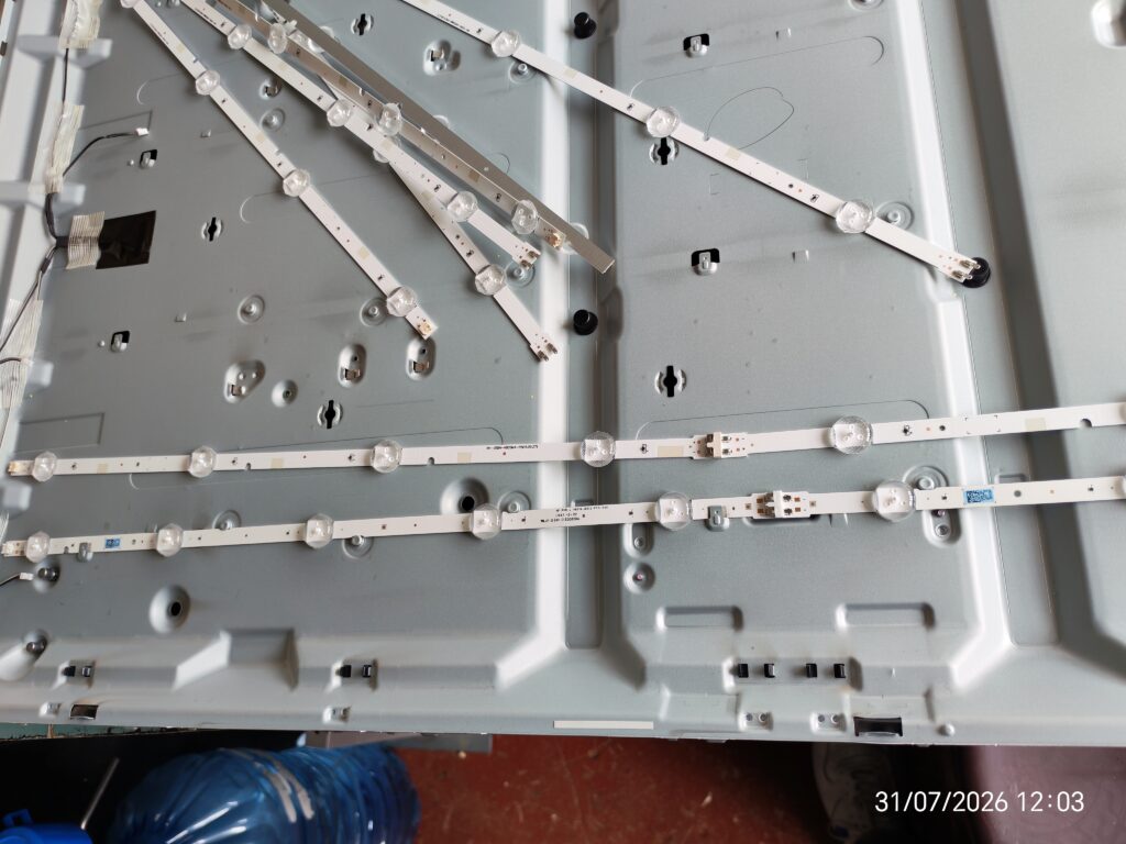
The fundamental purpose of the backlight is simple:
It provides illumination for the LCD panel.
An LCD pixel does not normally generate the visible light itself. Instead, the liquid-crystal layer controls the transmission of light coming from the illumination system behind it.
The basic optical path can be represented as:
LED LIGHT SOURCE → DIFFUSER → OPTICAL FILMS → LCD CELL → COLOUR FILTER → VIEWER
The backlight therefore provides the light that ultimately becomes the visible television image.
Without illumination, the LCD panel can continue receiving image information, but the viewer may see a black or extremely faint screen.
3. LCD PANEL VERSUS BACKLIGHT
It is important not to confuse the LCD panel with the backlight.
The LCD panel is responsible for controlling the individual pixels.
The backlight supplies illumination.
The T-CON board generally handles timing and distributes image data to the panel electronics.
The mainboard processes video signals, controls television functions and communicates with other boards.
The power supply board provides electrical power to different sections of the television.
The LED driver circuit regulates the electrical supply required by the LED backlight system.
These systems work together.
A simplified chain is:
VIDEO SOURCE → MAINBOARD → T-CON/PANEL → PIXELS
while simultaneously:
POWER SUPPLY → LED DRIVER → LED BACKLIGHT → OPTICAL SYSTEM
The viewer sees the result of both systems working together.
4. WHY MODERN TVs USE LED BACKLIGHTS
Older LCD televisions commonly used fluorescent illumination, particularly CCFL technology.
Modern televisions predominantly use LEDs because LED systems can be:
- More compact
- More energy efficient
- Easier to control electronically
- Capable of producing high brightness
- Suitable for thin television designs
- Compatible with local-dimming systems
- Available in many configurations
LED technology also allows manufacturers to produce very thin televisions.
5. WHAT IS AN LED STRIP?
An LED strip is a long circuit board or flexible substrate containing multiple LEDs.
In television panels, the strips are positioned so that their light illuminates the display area.
Depending on the television design, the strips may be mounted:
- Behind the LCD panel
- Along the edges of the display
- On a metal chassis
- In specially designed channels
The exact arrangement depends on the television's backlight architecture.
6. DIRECT-LIT BACKLIGHT
In a direct-lit design, LEDs are positioned behind the LCD panel.
The LEDs illuminate the panel from the rear.
This arrangement can provide relatively even illumination when the optical system is correctly designed.
A simplified arrangement is:
LCD PANEL
DIFFUSER / OPTICAL LAYERS
LED STRIPS
METAL CHASSIS
Direct-lit systems are common in many conventional LED televisions.
7. EDGE-LIT BACKLIGHT
In an edge-lit television, LEDs are positioned around the edges of the display rather than distributed across the entire rear surface.
Light is directed through a light-guide plate.
The arrangement can be represented as:
LCD PANEL
OPTICAL FILMS
LIGHT GUIDE PLATE
EDGE LEDs
Edge lighting allows manufacturers to produce extremely thin displays.
However, the optical design must distribute the light correctly across the entire screen.
8. FULL-ARRAY BACKLIGHTING
Full-array backlighting places multiple LED sources across the rear of the display.
This architecture provides greater control over different regions of the screen.
Some televisions combine full-array LED illumination with local dimming.
9. LOCAL DIMMING
Local dimming allows different groups or zones of LEDs to operate at different brightness levels.
For example, a dark region of an image can receive less backlight while a bright region receives more.
This can improve perceived contrast.
However, the effectiveness of local dimming depends on the number of zones, panel characteristics, processing algorithms and optical design.
10. BACKLIGHT BRIGHTNESS CONTROL
The television does not necessarily operate the backlight at maximum brightness continuously.
The main control system can adjust the backlight level.
Brightness can be affected by:
- User picture settings
- Energy-saving settings
- Ambient-light sensors
- Picture mode
- Dynamic contrast processing
- Local-dimming algorithms
- Thermal protection
- LED-driver feedback
The exact control architecture differs by manufacturer and model.
11. THE LED DRIVER
The LED driver is responsible for supplying the appropriate electrical conditions to the LED strings.
LEDs cannot simply be connected directly to an arbitrary power source.
The driver controls electrical parameters such as current and, depending on the design, voltage.
A simplified concept is:
POWER SUPPLY → LED DRIVER → LED STRING
The driver monitors the backlight system and may shut it down if it detects an abnormal condition.
12. WHY LED STRINGS ARE CONNECTED IN SERIES
Many television backlight designs use multiple LEDs connected in series.
In a series string, the same current passes through each LED.
The total forward voltage is approximately related to the combined forward voltage of the LEDs.
For example, if a string contains several LEDs, the driver may need to produce a substantially higher voltage than that required by one individual LED.
This is one reason technicians should never assume that the LED output voltage is equivalent to the voltage of a single LED.
13. BACKLIGHT PROTECTION
Modern LED drivers commonly include protection mechanisms.
Possible protection functions include:
- Over-voltage protection
- Over-current protection
- Open-string detection
- Short-circuit protection
- Thermal protection
If one LED string becomes open, the driver may detect the abnormal condition and shut down the backlight.
This can result in a television that briefly illuminates the screen and then becomes dark.
14. THE CLASSIC “FLASH THEN DARK” FAULT
One common backlight symptom is:
The TV powers on → screen flashes briefly → backlight goes off.
This does not necessarily mean the entire television has failed.
Possible causes include:
- Open LED
- Damaged LED strip
- Poor connector contact
- LED-driver fault
- Power-supply fault
- Incorrect feedback signal
- Protection shutdown
Diagnosis requires measurement and testing rather than replacing parts based solely on symptoms.
15. SOUND BUT NO PICTURE
Another common symptom is:
Television has sound but screen appears black.
This is a classic symptom that requires systematic diagnosis.
Possible causes include:
- Failed LED backlight
- LED-driver problem
- Power-supply problem
- LCD panel fault
- T-CON fault
- Mainboard fault
- Incorrect display settings
- Cable or connector problem
A flashlight test can sometimes help distinguish an illumination problem from an image-generation problem.
16. THE FLASHLIGHT TEST
With the television operating, a technician can shine a bright flashlight toward the screen at an angle.
If a very faint image or menu can be seen, that suggests the LCD panel may still be generating an image while the backlight is not illuminating it properly.
This test is only a diagnostic indication.
It does not identify the exact defective component.
For example, the fault could still be in the LED strips, LED driver, power supply or associated wiring.
17. WHY THE SCREEN CAN STILL HAVE AN IMAGE WITHOUT BACKLIGHT
The LCD system may still be controlling the pixels even when the illumination has failed.
Because the image is extremely dark without backlight illumination, it may appear as if there is no picture.
The flashlight provides an external light source that makes the faint image easier to see.
18. INDIVIDUAL LED FAILURE
A single LED can fail in different ways.
It may become:
- Open circuit
- Short circuit
- Intermittent
- Thermally unstable
- Physically damaged
An open LED in a series string can prevent current from flowing through the entire string.
A shorted LED can allow the remaining LEDs to operate but can alter the optical output and electrical characteristics.
19. WHY ONE FAILED LED CAN AFFECT THE WHOLE SCREEN
Suppose a backlight string contains many LEDs connected in series.
If one LED becomes open:
LED 1 → LED 2 → LED 3 → OPEN LED → LED 5 → LED 6
Current cannot flow through the complete series path.
The driver may therefore detect an open circuit and shut down the string.
As a result, the entire television backlight may turn off.
20. LED STRIP REPLACEMENT
When backlight strips fail, technicians may replace:
- Individual LEDs
- One strip
- Multiple strips
- The complete backlight strip set
The appropriate repair depends on the construction of the television, available parts, repair objectives and condition of the remaining LEDs.
Replacing only one failed LED can sometimes be possible, but it requires suitable equipment and skill.
21. WHY COMPLETE STRIP REPLACEMENT IS OFTEN CONSIDERED
If one LED has failed because of age or thermal stress, other LEDs in the same television may also have significant operating hours.
Replacing the complete set can provide more consistent illumination.
However, the correct repair depends on the specific television and parts availability.
22. LED LENS PROBLEMS
Many television LEDs have small optical lenses placed over them.
These lenses spread the light over the required area.
If an LED lens becomes loose or detached, the screen may develop a bright circular spot.
This can appear as:
- White spots
- Bright patches
- Uneven illumination
- Circular light marks
The LED itself may still be electrically functional.
23. WHITE SPOTS ON THE SCREEN
White spots are often associated with optical components above individual LEDs.
A detached lens can concentrate light into one area rather than distributing it correctly.
This can create visible bright spots when the television displays a light-coloured image.
24. DARK AREAS
Dark areas can result from:
- Failed LEDs
- Failed sections of LED strips
- Poor connections
- Optical-layer problems
- Panel-related faults
The location and pattern of the dark area can provide useful diagnostic information.
25. UNEVEN BACKLIGHT
A television may operate but display uneven brightness.
Possible symptoms include:
- Dark corners
- Bright patches
- Vertical dark sections
- Horizontal dark sections
- Clouding
- Light leakage
- Unequal illumination
Diagnosis requires consideration of both the LED system and optical layers.
26. BACKLIGHT DIFFUSER
The diffuser helps spread light from the LEDs.
Without proper diffusion, individual LEDs would create obvious bright points rather than producing relatively uniform illumination.
The diffuser is therefore a critical optical component.
27. OPTICAL FILMS
LCD television displays can contain several optical films.
Their functions can include:
- Light diffusion
- Light distribution
- Brightness enhancement
- Directional control
- Uniform illumination
These films must be handled carefully during panel disassembly.
28. WHY PANEL DISASSEMBLY IS HIGH RISK
Opening an LCD television to replace the backlight requires removal of the display panel and optical layers.
The LCD glass is extremely thin and fragile.
Damage can occur from:
- Bending
- Twisting
- Uneven lifting
- Pressure
- Dropping
- Incorrect handling
- Contamination
- Misalignment
A technician can successfully repair the LEDs but accidentally damage the LCD panel during disassembly.
29. PANEL HANDLING
The panel should generally be handled with appropriate support across its surface.
Avoid applying concentrated pressure to one section.
The exact handling procedure depends on the panel construction and television model.
30. BACKLIGHT REPAIR REQUIRES CAREFUL IDENTIFICATION
Before ordering LED strips, identify the television accurately.
Useful information includes:
- Brand
- Model number
- Screen size
- Panel number
- LED strip part number
- Number of LEDs
- Strip length
- Connector arrangement
Two televisions with the same screen size may use completely different LED strips.
31. SCREEN SIZE DOES NOT IDENTIFY THE LED STRIPS
A 43-inch television from one manufacturer may use a completely different backlight system from another 43-inch television.
Even two models from the same brand can use different strips.
Therefore:
Never order backlight strips using screen size alone.
32. PANEL NUMBER
The panel number can be extremely useful when identifying the correct backlight assembly.
It may be found on a label attached to the panel.
The exact identification method varies between manufacturers.
33. LED STRIP PART NUMBERS
Backlight strips can have identifying codes printed on the strip.
A technician should compare:
- Part number
- Number of LEDs
- Physical length
- Connector
- Mounting holes
- LED spacing
- Electrical specifications
34. TESTING BACKLIGHT STRIPS
Technicians may use specialized LED backlight testers to test LED strings.
A tester can help identify:
- Open strings
- Abnormal voltage
- Individual LED problems
- String behaviour
Testing equipment must be used according to its specifications.
35. MULTIMETER TESTING
A multimeter can sometimes assist with LED testing, but its usefulness depends on the meter's diode-test capability and the construction of the backlight.
A standard continuity test is not always appropriate for an entire television LED string because the string may require a much higher voltage to conduct.
36. LED BACKLIGHT TESTER
A dedicated LED tester can apply an appropriate test voltage/current to a backlight string.
This can be useful for determining whether a strip illuminates and whether its electrical behaviour is abnormal.
37. DO NOT SHORT LEDS RANDOMLY
Shorting failed LEDs can be used as a temporary diagnostic technique in some repair contexts, but indiscriminate bypassing is not a reliable long-term repair.
The LED was part of the designed electrical and optical system.
Bypassing it changes:
- String voltage
- Optical output
- Electrical stress
- Thermal distribution
A proper replacement is generally preferable where practical.
38. LED CURRENT
LED lifespan is strongly affected by operating conditions, including current and temperature.
Excessive LED current can increase:
- Junction temperature
- Thermal stress
- Light output initially
- Long-term degradation
This is one reason correct driver operation matters.
39. HEAT AND LED LIFE
Heat is a major consideration in LED reliability.
LEDs convert electrical energy into light and heat.
Poor thermal management can accelerate degradation.
Television designers therefore use:
- Metal chassis
- Heat-spreading structures
- Thermal interfaces
- Current regulation
- Mechanical ventilation
depending on the design.
40. WHY BACKLIGHTS FAIL OVER TIME
Backlight failure can result from cumulative operating stress.
Possible factors include:
- Long operating hours
- High brightness settings
- Elevated temperature
- LED degradation
- Power-supply abnormalities
- Poor thermal transfer
- Manufacturing variation
- Mechanical damage
A television that operates many hours every day may experience greater cumulative stress than one used occasionally.
41. HIGH BACKLIGHT SETTINGS
Operating the television at maximum backlight brightness continuously can increase LED operating stress.
For long-term use, moderate brightness settings may reduce unnecessary stress, although the appropriate setting depends on the room and viewing requirements.
42. ENERGY-SAVING MODES
Many televisions provide energy-saving settings that reduce illumination.
These settings can reduce power consumption.
The exact effect varies by manufacturer.
43. AUTOMATIC BRIGHTNESS CONTROL
Some televisions use ambient-light sensors or software controls to adjust display brightness according to room conditions.
This can reduce unnecessary backlight output in darker environments.
44. BACKLIGHT POWER CONSUMPTION
The backlight can represent a significant portion of the television's electrical consumption.
Larger screens generally require more illumination power, although actual consumption varies considerably by technology and model.
45. BACKLIGHT AND SCREEN SIZE
A larger television normally requires a larger illuminated area.
However, screen size alone does not determine backlight power.
Factors include:
- LED efficiency
- Number of LEDs
- Drive current
- Brightness target
- Optical efficiency
- Panel transmission
- Local-dimming architecture
46. BACKLIGHT AND HDR
High Dynamic Range content can require substantially higher peak brightness than ordinary SDR content.
Modern televisions may therefore drive the backlight differently during HDR playback.
The exact implementation depends on the display technology.
47. BACKLIGHT AND CONTRAST
Backlight control can influence perceived contrast.
Reducing illumination behind dark portions of an image can make blacks appear darker.
This is one reason local dimming is used in some LCD televisions.
48. BACKLIGHT BLEED
Backlight bleed refers to unwanted illumination visible around parts of the display, particularly near edges or corners.
Some degree of variation can occur due to panel construction.
Excessive or newly developed bright areas can indicate mechanical or optical problems.
49. CLOUDING
Clouding refers to uneven patches of brightness visible particularly on dark screens.
Potential causes include panel uniformity characteristics, optical structure, pressure, assembly variation or backlight distribution.
Not every example of clouding means that the LEDs themselves are defective.
50. BACKLIGHT AND LCD TECHNOLOGY
A conventional LCD/LED television uses an LCD imaging layer together with an LED illumination system.
This differs fundamentally from OLED displays.
In an OLED television, each pixel produces its own light.
Therefore, a conventional LED backlight replacement procedure does not apply to an OLED panel.
51. OLED DOES NOT USE A CONVENTIONAL BACKLIGHT
OLED pixels are self-emissive.
There is no separate LED backlight behind the OLED panel in the same way as an LCD/LED television.
This is an important distinction when diagnosing a television.
52. QLED AND BACKLIGHTS
Many televisions marketed as QLED are still LCD-based displays with an LED backlight and an additional quantum-dot layer.
Therefore, a QLED television can still have an LED backlight system.
The term “QLED” should not be confused with OLED.
53. MINI-LED BACKLIGHTING
Mini-LED televisions use a much larger number of smaller LEDs than conventional LED backlights.
This allows manufacturers to create more independently controlled illumination zones.
Mini-LED remains a backlit LCD technology.
54. FULL-ARRAY LOCAL DIMMING
Full-array local dimming can divide the backlight into independently controlled zones.
When correctly implemented, this can improve contrast in challenging scenes.
However, the number and size of zones affect the behaviour of the system.
55. EDGE-LIT VERSUS DIRECT-LIT
Edge-lit: LEDs positioned around the edge and light distributed through a guide.
Direct-lit: LEDs positioned behind the panel.
Full-array: A more extensive rear LED arrangement, often with multiple controllable regions.
Each architecture has different service considerations.
56. COMMON BACKLIGHT FAULT SYMPTOMS
A technician may encounter:
Complete black screen: possible complete backlight failure or another display fault.
Sound but no visible picture: possible backlight failure, among other causes.
Brief flash then darkness: possible LED-string protection shutdown.
Dark section: possible LED strip or optical problem.
Bright circular spots: possible detached LED lenses.
Flickering illumination: possible LED degradation, driver instability, poor connection or power problem.
Uneven brightness: possible LED, optical or panel-related issue.
57. SYSTEMATIC DIAGNOSIS
A good diagnosis should proceed logically.
First confirm that the television powers on.
Then establish whether:
- Audio works
- Remote commands work
- Menus are present
- Standby indicator behaves normally
- Screen briefly illuminates
- Flashlight test reveals an image
Then examine the power and backlight circuits.
58. DO NOT ASSUME EVERY BLACK SCREEN IS A BACKLIGHT FAULT
A black screen can also be caused by:
- Mainboard failure
- T-CON failure
- Panel failure
- LVDS/eDP-related connection problems
- Power supply failure
- Firmware problems
- Incorrect source/input conditions
Therefore, diagnosis should not stop at the first assumption.
59. POWER SUPPLY CHECKS
The technician should identify the relevant supply rails according to the service documentation or board markings.
The correct voltages vary significantly by television.
Measurements should be made using appropriate safety procedures.
60. HIGH-VOLTAGE CONSIDERATIONS
Some LED driver circuits operate at relatively high DC voltages.
The primary side of an AC power supply can also contain hazardous voltages.
A technician should not assume that unplugging the television immediately eliminates every electrical hazard.
Capacitors can retain charge.
Appropriate electrical safety practices are essential.
61. BACKLIGHT CONNECTORS
Connectors carry power from the driver or power board to the LED strips.
Faults can occur due to:
- Loose connections
- Oxidation
- Burn marks
- Mechanical damage
- Poor solder joints
- Overheating
A connector should be inspected carefully if the backlight behaves intermittently.
62. BURNT CONNECTORS
A discoloured or melted connector can indicate excessive heating.
Simply replacing the connector without identifying why it overheated may result in repeated failure.
63. LED STRIP SOLDER JOINTS
Some strips have soldered connections between sections.
Cracked joints can produce intermittent faults.
Thermal expansion and contraction can contribute to mechanical stress over time.
64. BACKLIGHT DRIVER FAILURE
The LED driver may fail independently of the LED strips.
Possible driver problems include:
- Switching transistor failure
- Controller IC failure
- Current-sense fault
- Feedback fault
- Capacitor degradation
- Transformer problems in certain architectures
- Open protection circuits
- Shorted semiconductor components
65. POWER BOARD AND BACKLIGHT DRIVER INTEGRATION
In many televisions, the LED driver is integrated into the power supply board.
In others, it may be a separate circuit or board.
Therefore, identifying the board architecture is important before ordering replacement parts.
66. MAINBOARD BACKLIGHT CONTROL
The mainboard may send an enable or dimming control signal to the LED driver.
Typical control concepts can include:
- BL-ON
- PWM DIM
- Analog DIM
The exact signal names and logic levels vary by design.
A missing control signal does not automatically prove that the mainboard is defective because another system may be preventing backlight activation.
67. PWM BACKLIGHT CONTROL
Pulse-width modulation can be used to control average LED brightness.
Instead of continuously reducing current in some designs, the system rapidly switches the LEDs on and off.
The proportion of on-time influences perceived brightness.
68. ANALOG DIMMING
Some LED systems also use an analog control signal to vary LED current.
Some designs combine PWM and analog current control.
69. BACKLIGHT DRIVER FEEDBACK
The driver can monitor the LED string to determine whether it is operating within expected parameters.
If the feedback indicates an abnormal condition, the driver may shut down.
This explains why some televisions repeatedly attempt to start the backlight and then turn it off.
70. CYCLING BACKLIGHT FAULTS
A defective LED string can cause repeated behaviour:
Start → illuminate → detect abnormality → shut down → restart attempt.
This can appear to the user as flickering or repeated flashes.
71. REPLACING BACKLIGHT STRIPS
A typical replacement procedure involves:
- Disconnecting the television from mains power.
- Removing the rear cover.
- Identifying the display panel and backlight architecture.
- Disconnecting relevant cables.
- Removing components obstructing panel removal.
- Carefully removing the LCD panel.
- Removing optical layers in the correct order.
- Accessing the LED strips.
- Replacing the damaged components.
- Reassembling the optical stack correctly.
- Testing the backlight.
- Testing the complete television.
The exact procedure varies substantially by model.
72. OPTICAL LAYER ORDER
The diffuser and optical films must be returned in their correct orientation and order.
Incorrect placement can cause:
- Uneven brightness
- Moiré-like patterns
- Dark areas
- Bright areas
- Reduced brightness
- Optical distortion
73. DUST CONTAMINATION
Dust or fingerprints between optical layers can become visible after reassembly.
A clean repair environment is therefore important.
74. PANEL PRESSURE
Excessive pressure during assembly can damage the LCD panel or create visible defects.
Technicians must avoid placing tools, screws or other objects where they can press against the panel.
75. WRONG SCREW PLACEMENT
Using an excessively long screw in the wrong location can damage the panel or internal optical components.
This is particularly important during reassembly.
76. LED STRIP ALIGNMENT
The strips must be positioned correctly.
Incorrect placement can change the illumination pattern.
77. LED LENS ALIGNMENT
LED lenses must be correctly positioned over their respective LEDs.
A displaced lens can create an obvious bright spot.
78. TESTING BEFORE FINAL REASSEMBLY
Where appropriate, technicians may perform controlled testing before completely reinstalling the rear cover.
However, exposed electronics present electrical hazards, so testing should be performed only by someone properly equipped and trained.
79. WHY PROFESSIONAL REPAIR MATTERS
Backlight replacement is not simply a matter of opening the TV and changing an LED strip.
The technician must deal with:
- Electrical diagnosis
- High-voltage sections
- Fragile LCD glass
- Optical films
- LED current
- Thermal considerations
- Correct parts identification
- Mechanical reassembly
A mistake can turn a repairable backlight fault into panel damage.
80. BACKLIGHT MAINTENANCE
There is no routine user procedure for physically servicing LED strips inside most televisions.
However, users can reduce unnecessary stress by:
- Avoiding excessive brightness continuously
- Keeping ventilation areas unobstructed
- Avoiding excessive heat
- Using appropriate picture settings
- Keeping the television clean externally
- Avoiding physical impact
81. TV VENTILATION
Heat must be able to escape from the television.
Do not block ventilation openings with:
- Cloth
- Furniture
- Wall structures
- Decorative materials
- Other equipment
Excessive heat can affect electronic components.
82. WALL-MOUNTED TELEVISIONS
A wall-mounted TV requires appropriate ventilation clearance according to its design.
The mounting arrangement should not obstruct required airflow.
83. BACKLIGHT AND TV AGE
As televisions accumulate operating hours, LEDs and other components can degrade.
A relatively old television with multiple backlight symptoms may require a broader assessment rather than replacing a single component without considering the remaining system.
84. BACKLIGHT AND PICTURE SETTINGS
Picture modes such as:
- Standard
- Dynamic
- Movie
- Cinema
- Sports
- Game
- Vivid
can use different brightness parameters.
Dynamic or vivid modes may operate the backlight more aggressively on some televisions.
85. BACKLIGHT FAILURE DOES NOT ALWAYS MEAN THE TV IS BEYOND REPAIR
A failed LED strip can be a repairable fault.
The economic decision depends on:
- TV size
- Panel condition
- Parts cost
- Labour
- Overall television condition
- Availability of replacement strips
- Age and model
- Other existing faults
86. BACKLIGHT REPAIR VERSUS PANEL REPLACEMENT
These are very different repairs.
Backlight repair: addresses illumination components.
Panel replacement: replaces the complete display assembly.
Panel replacement is usually substantially more extensive and depends heavily on part availability.
87. DIAGNOSING BACKLIGHT VERSUS PANEL FAILURE
A technician can use several observations:
- Flashlight test
- Backlight start behaviour
- Screen illumination
- Audio operation
- Menu visibility
- Test patterns
- Electrical measurements
- LED-string testing
No single observation should automatically determine the final diagnosis in every model.
88. BACKLIGHT AND T-CON DIAGNOSIS
The T-CON can be responsible for image-generation problems even when the backlight is working.
If the screen illuminates but has no image, the technician must investigate the video path rather than immediately replacing the LED strips.
89. BACKLIGHT AND MAINBOARD DIAGNOSIS
A defective mainboard can fail to command the LED driver.
This can result in no backlight even when the LED strips themselves are healthy.
90. BACKLIGHT AND POWER-SUPPLY DIAGNOSIS
If the power supply cannot provide the required energy to the LED driver, the backlight may fail.
Therefore, a backlight symptom does not always mean the LED strips themselves are defective.
91. DIAGNOSTIC LOGIC
A useful troubleshooting sequence is:
Does the television power on?
↓
Does audio operate?
↓
Does the screen briefly illuminate?
↓
Is a faint image visible with a flashlight?
↓
Is the LED driver receiving the required supply and control signals?
↓
Are the LED strings electrically intact?
↓
Is the panel receiving image data?
This approach reduces unnecessary part replacement.
92. BACKLIGHT REPAIR FOR SAMSUNG TVs
Samsung has used many different LCD/LED panel and backlight architectures.
Therefore, the exact model and panel identification are essential.
A Samsung television can use different LED strips depending on model, screen size and panel supplier.
93. BACKLIGHT REPAIR FOR LG TVs
LG LCD/LED televisions also use different backlight arrangements.
Some models use direct-lit systems while others use edge-lit or more advanced configurations.
Model identification is essential.
94. BACKLIGHT REPAIR FOR SONY TVs
Sony televisions can use different LED backlight architectures depending on model generation and display size.
The service approach should follow the specific model's construction.
95. BACKLIGHT REPAIR FOR TCL TVs
TCL has numerous television models using different panel and backlight designs.
Exact LED-strip identification is necessary.
96. BACKLIGHT REPAIR FOR HISENSE TVs
Hisense LCD televisions can use different strip configurations.
Technicians should identify the panel and strip part number before ordering replacements.
97. BACKLIGHT REPAIR FOR SKYworth TVs
Skyworth televisions also use various LED strip configurations.
Screen size alone is insufficient for selecting the correct replacement.
98. BACKLIGHT REPAIR FOR VITRON TVs
Vitron LCD/LED televisions may use different LED strips depending on model.
The exact model should be checked before replacement.
99. BACKLIGHT REPAIR FOR VISION PLUS TVs
Vision Plus televisions can have different panel and LED configurations.
Correct identification remains essential.
100. BACKLIGHT REPAIR FOR VON TVs
Von LCD/LED televisions may use different strip assemblies across models.
A technician should verify the exact model and panel information.
101. BACKLIGHT FAILURE AND PICTURE DIAGNOSIS
When a television develops a display problem, the first task is to determine whether the fault is actually related to illumination. A dark screen can result from several independent systems, so diagnosis should follow a structured process rather than relying on the appearance of the screen alone.
A technician should establish whether the television:
- Powers on normally
- Produces sound
- Responds to the remote
- Displays the startup logo
- Produces a brief flash of light
- Shows a faint image under external illumination
- Has functioning indicator lights
- Responds to menu commands
These observations help separate a backlight problem from a video-processing, panel, T-CON or power problem.
102. COMPLETE BACKLIGHT FAILURE
When all LED strings fail to illuminate, the screen may remain completely dark.
Possible causes include:
- Failed LED strips
- Failed LED driver
- Missing driver power
- Missing BL-ON command
- Power-supply failure
- Protection shutdown
- Open circuit
- Connector failure
A technician should determine which part of the backlight circuit has stopped functioning.
103. PARTIAL BACKLIGHT FAILURE
Sometimes only one section of the backlight fails.
The resulting picture may show:
- One dark side
- Horizontal dark areas
- Vertical dark areas
- A dark band
- Reduced brightness in one region
Partial failure can be particularly useful diagnostically because the remaining illuminated sections provide information about the system.
104. FLICKERING BACKLIGHT
A flickering backlight can indicate:
- Aging LEDs
- Poor electrical connections
- Driver instability
- Power-supply problems
- Thermal problems
- Intermittent LED-string faults
The technician should determine whether the flicker occurs continuously or only after the television has warmed up.
105. BACKLIGHT FAILURE AFTER WARM-UP
A television may initially operate correctly and then develop a dark screen after several minutes.
This can indicate a temperature-related fault.
Possible causes include:
- Thermal expansion
- Aging LED
- Weak solder joint
- Driver component overheating
- Protection activation
Testing the television while observing temperature-related behaviour can help identify the fault.
106. INTERMITTENT BACKLIGHT
An intermittent backlight is often more difficult to diagnose than a completely failed backlight.
The technician may need to observe:
- When the fault occurs
- Whether movement affects it
- Whether temperature affects it
- Whether brightness level affects it
- Whether restarting the television temporarily restores operation
Intermittent faults should not be dismissed simply because the television works during a brief test.
107. BRIGHTNESS DROPPING
If the television gradually becomes darker while operating, possible causes include:
- Thermal protection
- LED degradation
- Driver limitation
- Power-supply instability
- Software brightness control
- Faulty ambient-light sensing
The technician should establish whether the brightness reduction is intentional or abnormal.
108. SCREEN GOES DARK BUT SOUND CONTINUES
This symptom is frequently associated with the backlight system, but other possibilities remain.
A flashlight examination can help determine whether the LCD is still producing an image.
If a faint image remains visible, the illumination system becomes a strong area for investigation.
109. NO SOUND AND NO PICTURE
When both audio and display are absent, the technician should not begin by replacing LED strips.
The problem may instead involve:
- AC input
- Standby power
- Main power supply
- Mainboard
- Firmware
- Protection circuitry
- Shorted components
The diagnostic path is therefore different from a television that has working audio.
110. STANDBY LIGHT
The standby indicator can provide useful information.
Depending on the television, it may indicate:
- Standby mode
- Power-on status
- Protection condition
- Fault code through blinking
However, indicator behaviour differs between manufacturers.
111. BLINK CODES
Some television manufacturers use blinking LED patterns to indicate faults.
These codes can sometimes point toward:
- Power supply faults
- Mainboard faults
- Panel faults
- Backlight faults
The exact interpretation depends on the specific manufacturer and model.
112. SERVICE MANUALS
For advanced repair, the model-specific service documentation can provide:
- Board designations
- Test points
- Voltage specifications
- Connector pinouts
- LED-driver information
- Protection circuits
- Fault codes
- Disassembly information
Using model-specific documentation is preferable to relying on assumptions.
113. IDENTIFYING THE POWER BOARD
The power board commonly receives mains AC and generates various DC supplies.
Depending on the television, it may supply:
- Standby voltage
- Mainboard power
- Audio power
- LED-driver power
Some designs combine several functions on one board.
114. STANDBY POWER
Many televisions generate a standby supply even when the television appears to be switched off.
This allows the mainboard to detect the remote-control command and initiate startup.
115. POWER-ON SEQUENCE
A typical television startup can involve several stages:
AC INPUT
↓
STANDBY SUPPLY
↓
MAINBOARD STARTUP
↓
POWER-ON COMMAND
↓
MAIN POWER RAILS
↓
LED DRIVER ENABLE
↓
BACKLIGHT ACTIVATION
The exact sequence differs by design.
116. WHY SEQUENCE MATTERS
If the backlight does not activate, determining where the startup sequence stops can significantly reduce diagnostic time.
For example, if the main power rails never activate, replacing LED strips may accomplish nothing.
117. LED DRIVER STARTUP
Once the driver receives the appropriate power and enable command, it attempts to regulate the LED strings.
The driver may then monitor feedback.
If feedback is abnormal, it can disable the output.
118. OPEN-LED PROTECTION
An open LED string can trigger driver protection.
The driver may detect that the expected current is not flowing and shut down.
This is why a television can illuminate for only a moment before becoming dark.
119. SHORTED-LED PROTECTION
A short circuit in the LED system can also trigger protection.
The driver may detect abnormal current or voltage and stop operation.
120. LED STRIP CONNECTIONS
A television can contain multiple LED strings.
Depending on the design, they may be:
- Connected in series
- Divided into several series strings
- Connected to separate driver channels
The exact arrangement must be identified before testing.
121. SERIES STRINGS
In a series string, the current passes through each LED sequentially.
One open LED can therefore interrupt the entire string.
This electrical arrangement explains many complete-string failures.
122. PARALLEL ARRANGEMENTS
Some systems use multiple branches or strings.
A fault in one branch may affect only part of the backlight depending on the driver architecture.
123. LED FORWARD VOLTAGE
Each LED has a forward-voltage characteristic.
The exact value depends on:
- LED chemistry
- Current
- Temperature
- Manufacturer
- Construction
The total string voltage depends on the number of LEDs and their operating conditions.
124. WHY VOLTAGE MEASUREMENTS CAN BE MISLEADING
A technician may measure a high voltage at the LED connector and assume the LEDs are healthy.
That conclusion is not necessarily valid.
The driver may generate high voltage while attempting to start an open string.
Measurements must therefore be interpreted together with the circuit behaviour.
125. CURRENT REGULATION
The LED driver normally regulates current rather than simply applying an uncontrolled voltage.
This is important because LEDs are current-sensitive devices.
Excessive current can damage LEDs and shorten their operating life.
126. CURRENT-SENSE CIRCUIT
Many LED drivers use a current-sense resistor or related sensing circuit.
The driver monitors the voltage developed across the sensing element to regulate LED current.
A faulty current-sense circuit can therefore cause abnormal backlight behaviour.
127. PWM DIMMING
PWM allows brightness to be adjusted by changing the duty cycle of the control waveform.
For example, a higher duty cycle generally means the LEDs are active for a greater proportion of each cycle.
The actual implementation varies by television.
128. LED DRIVER IC
The driver may contain a dedicated integrated circuit that manages:
- Switching
- Current regulation
- Startup
- Feedback
- Protection
- Dimming
The surrounding components are also important because failure of a passive component can produce the same symptom as an IC failure.
129. SWITCHING TRANSISTORS
The driver can contain power semiconductors that switch energy at high frequency.
A failed switching transistor can cause:
- No backlight
- Fuse failure
- Short circuit
- Repeated startup
- Driver shutdown
Testing must follow the board's circuit design.
130. FUSES
Fuses can protect sections of the power and backlight circuits.
A blown fuse indicates excessive current or another fault condition.
Simply replacing a blown fuse without determining why it opened can lead to repeated failure.
131. CAPACITORS
Capacitors in power and driver circuits can deteriorate.
Possible symptoms include:
- Startup problems
- Instability
- Audible noise
- Intermittent operation
- Protection shutdown
Visual inspection can sometimes reveal damaged capacitors, but many capacitor failures are not visually obvious.
132. ELECTROLYTIC CAPACITORS
Electrolytic capacitors can lose capacitance or develop increased equivalent series resistance over time.
This can affect power-supply stability.
133. CERAMIC CAPACITORS
Ceramic capacitors can also fail, although the failure mechanisms differ.
A shorted ceramic capacitor can pull down a circuit rail and prevent normal operation.
134. TRANSFORMERS
Some LED-driver architectures use transformers or inductive components.
A defective transformer or associated switching circuit can prevent correct LED operation.
135. INDUCTORS
Inductors are common in switching converters.
An open or damaged inductor can interrupt the power path.
136. DIODES
Fast-recovery or Schottky-type diodes may be used in switching circuits.
A shorted diode can cause major power-supply problems.
137. PCB TRACK DAMAGE
Overheating or electrical faults can damage printed-circuit-board traces.
A visibly burned trace should be treated as evidence of an underlying fault rather than merely a cosmetic problem.
138. SOLDER JOINTS
Cracked solder joints can cause intermittent faults.
They may occur around:
- Heavy components
- Connectors
- Transformers
- Power semiconductors
- Heat-generating components
139. THERMAL STRESS
Repeated heating and cooling can create mechanical stress in solder joints and components.
This can contribute to intermittent operation over long periods.
140. LED STRIP THERMAL DESIGN
LED strips are normally mounted to structures that help transfer heat away from the LEDs.
Good thermal contact is important.
141. THERMAL PADS AND ADHESIVES
Some designs use adhesive layers or thermal interfaces between LED strips and the chassis.
Improper replacement can affect thermal performance.
142. LED LENS ADHESION
LED lenses may be attached using adhesive.
When the adhesive fails, the lens can shift or detach.
This can produce visible bright spots.
143. BRIGHT SPOT DIAGNOSIS
If the television has circular bright marks that correspond to individual LED positions, the optical lenses should be inspected.
This is different from a complete electrical backlight failure.
144. DARK SPOT DIAGNOSIS
A dark spot may result from:
- Failed LED
- Failed optical component
- Diffuser damage
- Panel damage
The location and appearance are important.
145. BACKLIGHT STRIP LENGTH
Replacement strips must match the original physical dimensions.
A strip that is electrically similar but mechanically different may not fit correctly.
146. NUMBER OF LEDS
The number of LEDs on a replacement strip matters because it affects:
- Total voltage
- Optical distribution
- Physical positioning
- Driver compatibility
147. LED SPACING
LED spacing affects optical uniformity.
Using an incorrectly spaced strip can produce nonuniform illumination even if the television technically operates.
148. CONNECTOR POLARITY
Correct connector orientation and polarity are essential.
Incorrect connection can damage components.
149. STRIP PART NUMBERS
A technician should record the strip's printed identification before ordering replacements.
Where possible, compare the replacement physically with the original.
150. PANEL IDENTIFICATION
The panel label can provide additional information.
The panel manufacturer and model may differ from the television brand.
This is particularly important because television manufacturers can source panels from different suppliers.
151. PANEL SUPPLIERS
Different television models may use panels supplied by different manufacturers.
Consequently, two televisions carrying the same external brand name can have different internal display assemblies.
152. WHY MODEL NUMBERS MATTER
A television model number identifies a particular design family.
It is more useful than simply saying:
“55-inch Samsung TV.”
A proper repair request should ideally include the full model number.
153. SERIAL NUMBERS
Serial numbers can sometimes help identify manufacturing batches or regional variants.
They can be useful when communicating with manufacturers or parts suppliers.
154. REGIONAL VARIATIONS
Televisions sold in different markets can have different:
- Power supplies
- Tuners
- Firmware
- Panel assemblies
- Mainboards
- Backlight components
This is another reason exact identification matters.
155. IMPORTED USED TELEVISIONS
Second-hand televisions may have components different from those expected for the local market.
A technician should inspect the actual television rather than relying only on an online parts catalogue.
156. USED TV BACKLIGHT INSPECTION
Before selling a second-hand television, a proper inspection can include:
- Screen uniformity
- Brightness
- Colour reproduction
- Backlight operation
- HDMI inputs
- Audio
- Remote operation
- Wi-Fi where applicable
- USB ports
- Tuner operation
- Physical condition
157. SCREEN UNIFORMITY TEST
Displaying a series of solid-colour images can reveal:
- Dark areas
- Bright spots
- Uneven illumination
- Dead pixels
- Colour abnormalities
A black test image can make some backlight uniformity problems easier to identify.
158. WHITE TEST SCREEN
A white image can reveal uneven brightness and colour variation.
Technicians can compare different sections of the display.
159. GREY TEST PATTERNS
Grey test patterns are particularly useful for identifying subtle uniformity problems.
They can reveal clouding, bands and uneven illumination.
160. RED, GREEN AND BLUE TESTS
Individual colour screens can help identify pixel and colour-channel abnormalities.
A complete television assessment should not rely on a single test image.
161. DEAD PIXELS
A dead pixel is different from a backlight failure.
A dead pixel involves the display element itself.
Backlight replacement generally does not repair dead pixels.
162. STUCK PIXELS
A stuck pixel may remain permanently at a particular colour or brightness state.
Again, this is fundamentally different from an LED backlight problem.
163. PANEL CRACKS
A cracked LCD panel is generally a major display-assembly problem.
Replacing the backlight will not repair a cracked LCD glass layer.
164. PRESSURE DAMAGE
Pressure marks can result from mechanical stress on the LCD panel.
They may appear as dark areas, coloured patches or irregular patterns.
165. WATER DAMAGE
Liquid entering a television can damage:
- Backlight connectors
- Power boards
- Mainboards
- Panel electronics
- T-CON circuits
- LED strips
A television with liquid damage should be assessed carefully before energizing it.
166. DUST AND INSECTS
Dust and insects can enter ventilation openings.
Contamination can affect circuit boards and connectors.
Cleaning should be done using appropriate electronics-service methods.
167. POWER SURGE DAMAGE
Electrical surges can damage:
- Power supply
- LED driver
- Mainboard
- HDMI circuitry
- Panel electronics
A television that stopped working after a major electrical event requires a broader inspection.
168. LIGHTNING DAMAGE
Lightning-related electrical events can produce extensive damage.
The fault may not be limited to the backlight.
169. VOLTAGE FLUCTUATIONS
Repeated abnormal supply conditions can stress power electronics.
Proper electrical protection can reduce risk, although no protection system eliminates every possible failure.
170. SURGE PROTECTION
Appropriate surge protection can help protect consumer electronics from certain transient events.
The protection device must be suitable for the electrical installation.
171. BACKLIGHT REPLACEMENT QUALITY
A high-quality replacement should match the original design as closely as practical.
Important factors include:
- LED arrangement
- Electrical characteristics
- Physical dimensions
- Connector
- Optical output
- Thermal design
172. CHEAP REPLACEMENT STRIPS
Very low-quality replacement strips may have inconsistent brightness or shorter operating life.
A repair should consider reliability rather than only immediate cost.
173. COMPLETE SET REPLACEMENT
Replacing the entire set of strips can provide consistent illumination across the panel.
It also reduces the possibility of mixing heavily aged LEDs with new ones.
174. INDIVIDUAL LED REPAIR
Individual LED replacement can sometimes be economical when suitable components and professional equipment are available.
However, it requires accurate component identification and careful optical alignment.
175. LED REWORK
Professional LED rework may require:
- Controlled heating
- Proper replacement LEDs
- Optical alignment
- Suitable soldering equipment
- Thermal management
- Testing
176. LED POLARITY
LEDs have polarity.
Incorrect installation can prevent operation or damage the component.
177. LED PACKAGE TYPES
Television LEDs are available in different physical packages and optical configurations.
A replacement LED must be compatible with the original application.
178. LENS ANGLE
The optical lens determines how light spreads.
An LED with a different optical characteristic can produce an uneven screen even if its electrical characteristics are acceptable.
179. COLOUR TEMPERATURE
Backlight LEDs are selected to provide a particular colour characteristic.
Changing LED characteristics can alter the display's overall appearance.
180. WHITE LED TECHNOLOGY
Most conventional LED-backlit LCD televisions use white LED illumination, often created using blue LEDs with phosphor conversion.
The exact implementation varies.
181. BLUE LED FAILURE
Because many white LEDs use blue LED chips with phosphor conversion, degradation of the LED can affect both brightness and colour characteristics.
182. PHOSPHOR DEGRADATION
Long-term operation can alter LED phosphor characteristics.
This can contribute to changes in brightness and colour.
183. BACKLIGHT AGEING
Backlight ageing is gradual.
A television does not necessarily move directly from “perfect” to “dead.” Brightness can decline over many operating hours.
184. UNEVEN AGEING
Different LEDs can age at different rates.
This can produce nonuniform illumination.
185. BACKLIGHT CALIBRATION
After repair, picture settings may need to be checked.
The television should produce appropriate brightness across different test images.
186. REPAIR VERIFICATION
After backlight repair, a technician should verify:
- Startup
- Stable illumination
- Full-screen brightness
- Uniformity
- Picture reproduction
- Audio
- Inputs
- Remote operation
- Extended operation
187. EXTENDED TESTING
A television should ideally be observed for sufficient time to identify thermal or intermittent problems.
A unit that works for two minutes may still fail after extended operation.
188. TESTING DIFFERENT BRIGHTNESS LEVELS
The backlight should be observed at different brightness settings.
This can reveal faults that only appear at high output.
189. TESTING DIFFERENT CONTENT
Different images can reveal different faults.
Useful content includes:
- Black
- White
- Grey
- Red
- Green
- Blue
- Normal television programming
- High-contrast scenes
190. FINAL BACKLIGHT ASSESSMENT
A proper backlight diagnosis should answer three questions:
Is the backlight receiving the correct power?
Are the LED strings electrically functional?
Is the driver receiving the correct control and feedback conditions?
Once these questions are answered, the technician can narrow down the defective section much more accurately.
191. BACKLIGHT REPAIR AS A PROFESSIONAL SERVICE
Backlight repair is a specialized television service because it combines electrical troubleshooting with delicate display-panel handling.
It requires more than replacing visible components.
A successful repair must restore:
- Electrical operation
- Optical uniformity
- Brightness
- Reliability
- Mechanical integrity
192. FINAL OBSERVATION
The most important diagnostic principle is:
A dark television screen is a symptom, not a diagnosis.
The technician must determine whether the problem originates from the LED strips, LED driver, power supply, mainboard, T-CON, panel, wiring or another part of the display system.
This systematic approach is applicable across many LCD/LED television brands, including Samsung, LG, Sony, TCL, Hisense, Skyworth, Vitron, Vision Plus, Von, Panasonic, Philips, Toshiba, JVC, Sharp, Xiaomi, Haier, Changhong, Konka, StarTimes, Bruhm, Mika and other LED/LCD television brands, although the internal architecture varies by model.