
Electrical equipment (0723763173) depends on a suitable power supply to operate correctly. When the incoming voltage is outside the acceptable operating range of connected equipment, problems can occur, including unexpected shutdowns, equipment malfunction, excessive heating and interruptions to business operations.
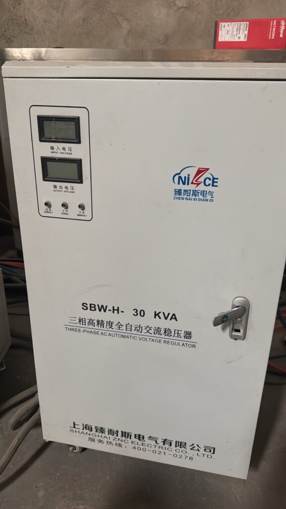
A power stabilizer, also called a voltage stabilizer, is designed to regulate voltage within a specified operating range. Depending on its design, it may use relays, servo-driven mechanisms, electronic switching circuits or other control technologies to adjust its output.
However, a stabilizer is not a universal solution to every electrical problem. It cannot compensate for every supply disturbance, correct defective building wiring or guarantee protection against lightning and severe electrical surges. Selecting the correct equipment and installing it properly are essential.
Pro-Logic Technologies Limited provides electrical and electronics repair enquiries, including power stabilizer diagnosis, repair, installation and maintenance enquiries in Nairobi, Kenya.
Customers may require assistance with stabilizers that do not switch on, produce no output, display incorrect voltage readings, fail to regulate voltage, trip repeatedly or overheat during operation.
The appropriate repair depends on the stabilizer's design, rated capacity, input-voltage range, output requirements and the actual fault identified during testing.
Contact Pro-Logic Technologies Limited on 0723763173 to discuss power stabilizer repair and installation requirements.
2. What Is a Power Stabilizer?
A power stabilizer is an electrical device designed to maintain its output voltage within a specified range despite changes in the incoming supply voltage.
For example, a stabilizer designed for a nominal 230 V supply may adjust its output when the incoming voltage rises or falls, provided that the input remains within its specified operating limits and the connected load does not exceed its rated capacity.
The exact input and output ranges depend on the model. Not every stabilizer can operate effectively under severe undervoltage, extreme overvoltage or unstable frequency conditions.
A stabilizer may include voltage-sensing circuitry, a control circuit, switching components, a transformer or autotransformer, protective devices and an output monitoring system.
More advanced units may also include digital displays, programmable limits, alarms, cooling fans and automatic shutdown functions.
The purpose of these components is to regulate voltage and help maintain a suitable electrical supply for compatible equipment.
3. Why Power Stabilizer Repair Is Important in Nairobi
Power stabilizers are used in residential, commercial and industrial environments. Their applications include compatible televisions, refrigeration equipment, office electronics, laboratory equipment and selected machinery.
A faulty stabilizer may stop providing power, supply an incorrect voltage or interrupt the operation of connected equipment.
For a business, this can lead to downtime and disrupted operations. In a home, it may prevent appliances from operating normally.
Repairing a stabilizer can be a practical option when the defect is identifiable, suitable replacement components are available and the cost of repair is reasonable compared with replacement.
However, a damaged unit should not automatically be repaired without considering its condition. Severe transformer damage, extensive overheating, deteriorated insulation or repeated failures may make replacement the safer or more economical choice.
A proper technical assessment should establish the likely cause, repair options and expected cost before work is authorized.
4. Common Power Stabilizer Problems
Power stabilizers can develop different faults depending on their construction, operating conditions, maintenance history and the quality of the electrical supply.
Common problems include:
- Stabilizer does not switch on.
- Stabilizer powers on but produces no output.
- Output voltage is too low.
- Output voltage is too high.
- Output voltage fluctuates continuously.
- Stabilizer repeatedly switches between voltage levels.
- Relay clicks continuously.
- Servo motor does not move.
- Digital display shows an error.
- Voltage display readings appear incorrect.
- Stabilizer overheats during operation.
- Cooling fan fails to operate.
- Circuit breaker or protective device trips repeatedly.
- Stabilizer produces unusual buzzing or mechanical noise.
- Transformer becomes excessively hot.
- Burnt smell or visible component damage.
- Stabilizer shuts down under load.
- Unit operates without regulating voltage correctly.
These symptoms are useful starting points for diagnosis, but they do not independently establish which component has failed.
For example, no output may result from a defective control circuit, an open protective device, a transformer fault, damaged wiring or a shutdown condition triggered by the stabilizer's protection system.
The technician should identify the actual fault before replacing components.
5. Power Stabilizer Repair in Nairobi CBD
Nairobi CBD contains residential buildings, retail premises, offices, workshops and businesses that rely on electrical equipment.
A faulty stabilizer in these environments may interrupt computer use, display equipment, refrigeration or other compatible electrical loads.
Customers seeking power stabilizer repair in Nairobi CBD should provide the stabilizer's make, model, rated capacity and fault symptoms when requesting an assessment.
Where possible, also provide the rated input voltage, output voltage and whether the fault occurs immediately or only when equipment is connected.
For example, a stabilizer that works without a load but shuts down when an appliance is connected may have a different problem from a stabilizer that cannot produce any output.
The reported symptoms help guide the initial investigation, although electrical measurements may still be required.
Workshop: Luthuli Avenue, Kangari Building, 3rd Floor, Room KA7, Nairobi.
Telephone: 0723763173.
Customers should confirm workshop arrangements and any available collection or on-site service before transporting equipment.
6. Automatic Voltage Regulator Repair in Nairobi
An Automatic Voltage Regulator, commonly called an AVR, is designed to regulate voltage automatically within its specified operating limits.
The term AVR is used for different types of equipment, including standalone stabilizers and voltage-regulation systems integrated into generators or other electrical installations. Their designs and repair procedures are not identical.
Standalone stabilizers may use relay switching, servo mechanisms or electronic regulation. Generator AVRs control generator excitation and require a different diagnostic approach.
Before repair begins, the technician should establish which type of regulator is involved.
For a standalone stabilizer, diagnosis may involve voltage-sensing circuitry, control boards, relays, transformers, motors and protective components.
For a generator AVR, diagnosis may involve the regulator's excitation circuit, sensing inputs, connections and compatibility with the generator.
The correct procedures depend on the equipment's design and technical documentation.
7. Power Stabilizer Installation Services
Correct installation is as important as selecting the right stabilizer.
An undersized stabilizer may shut down under load, overheat or fail to support equipment with high starting-current requirements. An incorrectly wired installation can create electrical hazards or prevent the stabilizer from operating as intended.
Installation planning should consider the following factors:
Connected load: Determine the power consumption of the equipment that will be supplied by the stabilizer.
Starting current: Refrigerators, pumps, compressors and motors can draw substantially more current during startup than during normal operation.
Rated capacity: Select a stabilizer whose capacity is suitable for the actual load and operating conditions.
Input-voltage range: Confirm that the stabilizer can operate within the voltage conditions at the installation location.
Output requirements: Check the voltage, frequency, phase configuration and other electrical requirements of the connected equipment.
Protection: Provide appropriate circuit protection, wiring and earthing according to the installation design and applicable electrical requirements.
Ventilation: Allow sufficient clearance around the unit for cooling and servicing.
Accessibility: Install the equipment where inspection, operation and maintenance can be performed safely.
A qualified electrical professional should verify the installation before the connected equipment is placed into service.
8. Types of Power Stabilizers Serviced
The construction of a stabilizer determines how it regulates voltage and which components may require attention during repair.
8.1 Relay-Type Voltage Stabilizers
Relay-type stabilizers use switching components to select transformer taps or other voltage-adjustment arrangements.
They are commonly used for selected household and light commercial applications.
Potential faults include defective relays, worn contacts, damaged control circuits, loose connections and transformer-related problems.
Repeated clicking may indicate that the controller is responding to changing input voltage, but continuous switching can also result from a sensing fault or an unsuitable operating condition.
Diagnosis should establish whether the input voltage is fluctuating normally, whether the controller is functioning correctly and whether the switching components operate as intended.
8.2 Servo-Controlled Voltage Stabilizers
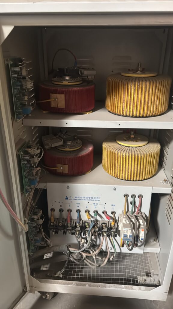
Servo-controlled stabilizers use a motor-driven mechanism to adjust voltage, commonly through a variable transformer arrangement.
The motor moves a mechanism to correct output voltage as the incoming supply changes.
Potential faults include a stalled servo motor, damaged drive circuitry, worn mechanical components, a defective position sensor or problems involving the voltage-sensing circuit.
Repair requires consideration of both electrical and mechanical components.
A motor that fails to move should not automatically be replaced until the technician determines whether the fault lies in the motor, controller, mechanical mechanism or associated wiring.
8.3 Electronic Voltage Stabilizers
Electronic stabilizers use electronic switching or power-control circuits to regulate voltage.
Depending on the design, they may contain semiconductor switches, control boards, sensing circuits, transformers and protective devices.
Possible faults include defective switching components, damaged control circuitry, power-supply problems and failed protection circuits.
Diagnosis requires the correct technical information and suitable test equipment.
8.4 Commercial Voltage Stabilizers
Commercial stabilizers supply compatible equipment used in offices, shops, workshops and other business environments.
Their capacity and design vary considerably.
Before repairing a commercial unit, establish its rated load, input-voltage range, output specification and the equipment it supplies.
If the stabilizer supports several machines, the combined demand and startup behaviour of those machines must be considered.
8.5 Industrial Voltage Stabilizers
Industrial stabilizers may serve larger electrical loads and can incorporate three-phase systems, substantial transformers, contactors, servo mechanisms and more complex protection circuits.
Industrial units require careful assessment of phase balance, load distribution, current ratings, cooling and installation conditions.
Work on these systems should be performed by suitably qualified personnel using the appropriate isolation and safety procedures.
9. Power Stabilizer Repair for Homes in Nairobi
Homeowners may use stabilizers with selected electronic appliances where the equipment manufacturer permits their use and the stabilizer is correctly rated.
A faulty household stabilizer can prevent an appliance from operating normally or cause unnecessary interruptions.
Before requesting repair, record the stabilizer's brand, capacity and the appliance connected to it.
If the stabilizer fails only when a refrigerator or other motor-driven appliance starts, the technician should consider the appliance's starting current and the stabilizer's capacity.
An unsuitable stabilizer may continue to trip even when its internal components are working correctly.
The solution may involve selecting a more appropriate unit rather than repairing a defective component.
10. Power Stabilizer Repair for Offices and Commercial Premises
Offices and commercial premises may depend on stable power for computers, printers, networking equipment, electronic displays and other compatible devices.
A stabilizer fault can interrupt work or affect several connected devices at once.
Commercial users should identify which equipment is connected, the total electrical demand and whether the problem affects the entire installation or only selected loads.
A technician can then assess the stabilizer and determine whether repair, replacement, load redistribution or a different power-protection arrangement is appropriate.
Where business continuity is important, customers should also consider whether the application requires additional protection such as surge protection or an uninterruptible power supply. These devices serve different functions and should be selected according to the actual requirement.
11. Power Stabilizer Maintenance and Preventive Servicing
Preventive maintenance can help identify problems before they cause a complete failure.
The appropriate maintenance interval depends on the stabilizer's design, operating environment, load and manufacturer's recommendations.
A maintenance assessment may include:
- Checking the exterior casing for damage.
- Inspecting accessible electrical connections.
- Checking ventilation and cooling arrangements.
- Examining displays and operating indicators.
- Assessing unusual noise or vibration.
- Checking output voltage under appropriate conditions.
- Inspecting switching or mechanical components where applicable.
- Reviewing fault history and repeated shutdowns.
- Confirming that connected loads remain within the rated capacity.
Internal inspection and electrical testing must be performed safely by qualified personnel.
Maintenance does not guarantee that a stabilizer will never fail, but it can help identify developing problems and support reliable operation.
12. How to Request Power Stabilizer Repair in Nairobi
When contacting a repair service, provide as much relevant information as possible.
Include the stabilizer's brand, model, capacity, input-voltage specification and the symptom you have observed.
Explain whether the unit produces no output, gives an unstable output, trips repeatedly or fails only when equipment is connected.
If the stabilizer is used with a refrigerator, air conditioner, pump or industrial machine, identify the connected equipment because starting current can influence stabilizer selection.
Do not open the stabilizer or touch internal wiring to obtain these details. Read information from the exterior label and provide measurements only if they have been obtained safely by a qualified person.
Contact Pro-Logic Technologies Limited
Telephone: 0723763173
Email: info@prologictechnologies.co.ke
Website: https://prologictecnologies.co.ke
Main workshop: Luthuli Avenue, Kangari Building, 3rd Floor, Room KA7, Nairobi.
Customers should confirm service availability, workshop arrangements and any applicable transport charges before proceeding.
PART 1 CONCLUSION
Power stabilizer repair and installation require a clear understanding of voltage regulation, connected load, equipment design and electrical safety.
A stabilizer that does not switch on, produces no output, overheats or fails to regulate voltage may have an internal fault, an unsuitable load or an installation-related problem. Correct diagnosis is necessary to distinguish between these possibilities.
Pro-Logic Technologies Limited welcomes enquiries concerning power stabilizer repair, voltage regulator diagnosis, installation and maintenance in Nairobi, Kenya.
13. Diagnosing a Power Stabilizer That Does Not Switch On
A power stabilizer that fails to switch on is one of the common faults encountered in voltage regulation equipment. The unit may have a completely blank display, no indicator lights, no output voltage or no response when the power switch is operated.
The underlying cause can range from an external supply problem to a defective internal component. A technician should establish the source of the fault before replacing parts.
13.1 Checking the Incoming Electrical Supply
The first diagnostic consideration is whether the stabilizer receives the correct incoming supply.
A faulty wall socket, damaged supply cable, disconnected circuit breaker or interruption in the electrical installation can prevent the stabilizer from operating.
The external supply should be checked using appropriate electrical testing procedures. If the installation has signs of damaged wiring, burning, sparking or repeated breaker trips, the problem should be assessed by a qualified electrician.
A stabilizer cannot regulate voltage when its incoming supply is absent or outside its permitted operating range.
13.2 Inspecting the Power Switch
Some stabilizers use a mechanical switch, while others use electronic switching or a combination of both.
A defective switch can interrupt the supply to the control circuit or prevent the unit from starting.
A technician can assess the switch and associated connections to determine whether it operates correctly.
The switch should not be bypassed as a substitute for repair because doing so can remove an important means of controlling or isolating the equipment.
13.3 Internal Fuse and Protection Circuit Diagnosis
A stabilizer may contain fuses, circuit breakers or other protective devices.
If a fuse has opened, the cause should be investigated before replacement. A fuse may operate because of an overload, short circuit, defective component or another abnormal condition.
Replacing a fuse without identifying the reason it failed can result in another failure.
The technician should inspect the relevant circuit, verify component condition and establish whether the protective device is suitable for the equipment.
13.4 Internal Power Supply Faults
Digital and electronically controlled stabilizers may contain an internal low-voltage power supply for the control board, display and sensing circuitry.
If this supply fails, the stabilizer may appear completely dead even when mains voltage reaches the unit.
Possible causes include defective semiconductor components, failed capacitors, damaged resistors or other faults within the control supply.
The correct repair depends on the stabilizer's circuit design and the results of electrical testing.
13.5 When Replacement May Be Preferable
Some stabilizers sustain extensive damage after overheating, moisture exposure or a severe electrical fault.
If the transformer, insulation system or several critical assemblies are badly damaged, replacement may be more practical than repair.
A technician should compare the estimated repair cost, replacement availability and condition of the existing unit before recommending a solution.
14. Power Stabilizer Has Input Power but No Output
A stabilizer may receive incoming power while providing no usable voltage to the connected equipment.
This condition requires careful diagnosis because different stabilizers use different control and protection arrangements.
14.1 Output Protection Has Activated
Some stabilizers disconnect their output when the incoming voltage is outside the supported range.
The unit may remain powered while displaying an error, alarm or abnormal input-voltage reading.
Check the manufacturer's operating limits and any displayed fault indication. If the incoming voltage is outside the specified range, the stabilizer may be behaving as designed rather than suffering an internal failure.
Persistent supply problems may require assessment of the electrical installation or the suitability of the selected stabilizer.
14.2 Output Relay Failure
Relay-controlled stabilizers may use relays to connect the regulated output to the load.
A defective relay, damaged contact or control fault can prevent output even when some internal circuits remain operational.
Diagnosis should establish whether the relay receives the correct control signal and whether its contacts operate as intended.
A relay should not be bypassed to force the stabilizer to provide output because this can expose connected equipment to unregulated voltage.
14.3 Output Wiring and Connector Faults
Loose terminals, damaged cables and deteriorated connections can interrupt the electrical path between the stabilizer and the connected load.
These faults may cause intermittent output, voltage drops or excessive heating at a connection.
Inspection should be performed with the equipment safely isolated and according to appropriate electrical procedures.
Damaged connectors and cables should be replaced with components suitable for the rated current and installation requirements.
14.4 Transformer-Related Faults
A defective transformer or autotransformer can prevent the stabilizer from delivering the required output.
Possible problems include an open winding, damaged insulation or an abnormal connection.
Testing should be performed using procedures appropriate to the transformer design. Insulation integrity and winding condition are important considerations when evaluating whether repair is practical.
15. Power Stabilizer Produces Low Output Voltage
Low output voltage may prevent connected equipment from operating correctly.
The fault can arise from an incoming supply problem, an incorrect stabilizer setting, a regulation failure, excessive load or an internal component defect.
15.1 Confirming the Voltage Reading
Before diagnosing an internal fault, establish whether the measured voltage is accurate.
A suitable calibrated meter should be used by a qualified person. The measurement must be made using the correct method for the equipment and electrical installation.
If the displayed voltage differs substantially from an independent measurement, the sensing or display circuit may require investigation.
15.2 Input Voltage Outside the Regulation Range
Every stabilizer has a defined input-voltage operating range.
When the incoming supply falls below the minimum permitted level, the stabilizer may be unable to maintain the rated output. Some units disconnect the load to protect equipment.
A stabilizer designed for moderate voltage variation may not be suitable for a location with severe undervoltage.
The correct solution may involve selecting equipment with an appropriate input range or addressing the underlying supply problem.
15.3 Overloaded Stabilizer
A stabilizer operating beyond its rated capacity may experience excessive voltage drop, overheating or protective shutdown.
The load should be evaluated in accordance with the manufacturer's rating, including any power-factor limitations and starting-current requirements.
A refrigerator, pump or compressor may demand a substantial starting current even when its normal running consumption appears modest.
If the stabilizer is undersized, reducing the load or selecting a suitably rated unit may be necessary.
15.4 Faulty Voltage Regulation Circuit
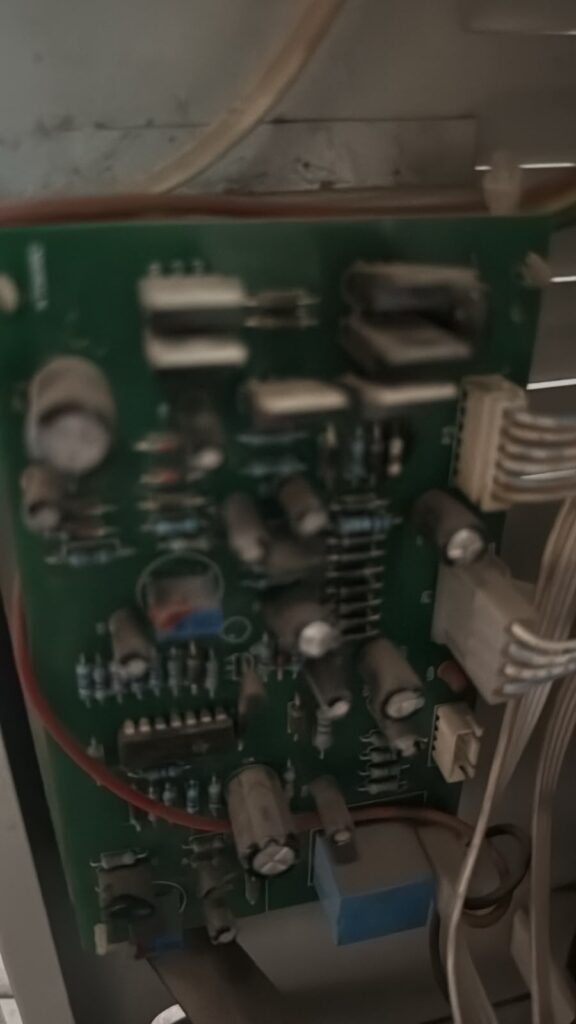
If the input supply is acceptable and the load remains within the rated capacity, the regulator's sensing and control systems may require testing.
Depending on the design, possible causes include a defective controller, failed switching components, incorrect feedback signals or a mechanical adjustment fault.
The appropriate repair should be based on measurements and the equipment's technical documentation.
16. Power Stabilizer Produces High Output Voltage
Excessive output voltage is a potentially serious fault because connected equipment may be damaged if the voltage exceeds its permitted operating range.
A stabilizer that supplies abnormally high voltage should be taken out of service until the fault has been assessed.
16.1 Faulty Voltage Sensing
The control system uses information about the incoming or output voltage to determine how regulation should occur.
If the sensing circuit provides an incorrect signal, the controller may select an inappropriate adjustment.
The technician should assess the sensing circuit and compare the measured voltage with the value recognized by the control system.
16.2 Relay or Switching Problems
In relay-controlled designs, defective contacts or a control fault can cause an incorrect transformer tap to remain connected.
In electronic designs, failed switching components or control signals may produce a similar regulation problem.
The correct diagnostic procedure depends on the stabilizer's topology.
16.3 Servo Control Failure
A servo-controlled stabilizer may produce an incorrect output if the motor, position feedback or control system fails to move the regulator to the required position.
The technician should assess the control signal, motor operation and adjustment mechanism.
Forcing the mechanism into another position or bypassing the control system can create dangerous output conditions.
16.4 Protecting Connected Equipment
Disconnecting the load safely and stopping further use are important when high output voltage is suspected.
Do not continue testing valuable appliances using a stabilizer that may be supplying excessive voltage.
After repair, the output should be verified using appropriate equipment under suitable operating conditions before the load is reconnected.
17. Power Stabilizer Output Voltage Keeps Fluctuating
A stabilizer should regulate output within its specified performance limits when operating within its permitted input range and load capacity.
Persistent fluctuations can indicate changing incoming voltage, excessive load, a control problem or a mechanical fault.
17.1 Incoming Voltage Fluctuations
Some voltage variation is expected in electrical networks, but severe or rapid fluctuations may exceed the stabilizer's regulation capability.
A technician should establish whether the incoming supply itself is changing significantly.
If the incoming voltage is unstable beyond the stabilizer's design limits, repairing the stabilizer alone may not resolve the problem.
17.2 Incorrect Voltage Feedback
The stabilizer's controller depends on voltage measurements to decide whether an adjustment is necessary.
A defective sensor, poor connection or unstable sensing supply can cause incorrect control decisions.
The technician should compare the actual voltage with the sensed or displayed value to identify inconsistencies.
17.3 Control Circuit Instability
A defective control board can cause unnecessary switching, delayed correction or unstable regulation.
Potential causes include damaged components, poor connections, supply instability or faults in the feedback circuit.
The repair process should identify the defective section rather than replacing the entire board without evidence.
17.4 Excessive Load Changes
Large or rapidly changing loads can affect stabilizer performance.
For example, a motor starting or a compressor switching on can cause a temporary increase in current demand.
The technician should evaluate the connected load and determine whether the stabilizer is correctly rated for the equipment's operating characteristics.
18. Relay-Type Power Stabilizer Repair in Nairobi
Relay stabilizers regulate voltage by switching between available transformer taps or other adjustment points.
They are used in selected household and commercial applications because their designs can be relatively straightforward.
However, relays and their associated control circuits can deteriorate over time or fail under unsuitable operating conditions.
18.1 Common Relay Stabilizer Faults
Potential problems include:
- Relay clicks continuously.
- Stabilizer produces no output.
- Output voltage remains too high or too low.
- Switching occurs irregularly.
- Contacts become damaged.
- Control circuitry fails to energize the correct relay.
- Connections overheat or become loose.
The presence of clicking alone does not prove that a relay is defective. It may reflect changing input voltage, a sensing fault or a controller attempting to correct an abnormal condition.
18.2 Relay Contact Deterioration
Repeated switching can gradually wear relay contacts, depending on the design and operating conditions.
Damaged contacts may create intermittent operation, excessive resistance or heat.
The technician should assess the relay and replace it with a compatible component where necessary.
Replacement relays must meet the required coil voltage, contact rating and other electrical specifications.
18.3 Relay Driver Circuit Problems
The control board may use transistor-based or other electronic driver circuits to energize relays.
If the driver fails, a relay may not operate even though the relay itself is healthy.
Diagnosis should include the control signal and associated circuitry rather than assuming that the relay is the only possible cause.
18.4 Relay Stabilizer Output Verification
Following repair, the technician should verify that the stabilizer responds correctly to the relevant input conditions and maintains output within the specified range.
The switching sequence, protection behaviour and output stability should be assessed according to the manufacturer's design.
19. Servo-Controlled Stabilizer Repair in Nairobi
Servo stabilizers use a motor-driven mechanism to adjust the regulated voltage.
Their construction may include a servo motor, mechanical transmission, variable transformer, position feedback system and electronic controller.
The combination of electrical and mechanical components requires diagnosis of both systems.
19.1 Servo Motor Does Not Move
If the motor remains stationary while the input voltage changes, the problem may involve the motor, drive circuit, controller, position sensor or mechanical mechanism.
The technician should determine whether the controller is issuing the correct command and whether the motor can respond under the specified operating conditions.
A motor should not be replaced solely because it fails to move. A defective controller or jammed mechanism can produce the same symptom.
19.2 Servo Motor Runs Continuously
A servo motor that continues moving without reaching a stable position may indicate a feedback problem or an unstable voltage-sensing signal.
A mechanical fault may also prevent the adjustment mechanism from reaching its intended position.
The diagnosis should establish whether the controller is receiving accurate feedback and whether the motor's movement corresponds to the required adjustment.
19.3 Worn Mechanical Components
Some servo stabilizers use mechanical contacts or moving components that may wear during extended use.
Deterioration can cause poor adjustment, intermittent operation or excessive noise.
Inspection should establish whether the affected components can be serviced or require replacement.
Lubrication, where applicable, should follow the manufacturer's recommendations rather than using arbitrary products.
19.4 Servo Control Board Repair
The servo controller determines how the motor responds to changes in voltage.
A defective sensing circuit, failed driver component or unstable control supply may cause incorrect operation.
The appropriate repair depends on the measured fault and the stabilizer's circuit design.
19.5 Final Testing of a Servo Stabilizer
After repair, the stabilizer should be assessed for correct motor movement, output regulation and protection behaviour.
Testing must remain within the equipment's specified operating limits.
The unit should not be returned to service until its operation has been verified and any identified safety concerns have been resolved.
20. Power Stabilizer Overheating and Burning Smell
Excessive heat can indicate overloading, poor ventilation, high connection resistance, transformer damage or a defective electronic component.
A burning smell should be treated as a warning sign rather than a routine operating condition.
20.1 Immediate Safety Measures
If a stabilizer produces smoke, a burning smell or visible sparks, stop using it.
Disconnect power only if doing so is safe. Do not touch exposed conductors or attempt to open the unit while it remains connected to the supply.
Arrange a qualified inspection before returning the stabilizer to service.
20.2 Overloaded Stabilizer
A stabilizer that supplies a load beyond its rated capacity may overheat.
The connected equipment should be identified and its demand compared with the stabilizer's specification.
If the stabilizer is undersized, replacing internal components will not correct the fundamental capacity problem.
20.3 Loose Electrical Connections
A loose or deteriorated connection can create a localized hot spot because of increased electrical resistance.
The technician should inspect the relevant connections while the equipment is safely isolated.
Damaged terminals, conductors or connectors should be repaired or replaced with suitably rated components.
20.4 Transformer Overheating
Transformer overheating may result from excessive load, abnormal input conditions, damaged windings or insulation deterioration.
The technician should determine whether the transformer is operating within its specified limits and whether its condition remains acceptable.
A severely damaged transformer may require replacement or may make replacement of the complete stabilizer more economical.
20.5 Cooling and Ventilation Problems
Restricted ventilation can increase internal temperature.
Ensure that the stabilizer is installed with the required clearances and that its ventilation openings remain unobstructed.
If the design includes a cooling fan, the fan and its control circuit may need inspection when abnormal temperature is reported.
21. Stabilizer Trips Repeatedly or Blows Fuses
Repeated tripping is a symptom that should be investigated rather than bypassed.
The protective device may be responding to an overload, short circuit, abnormal voltage or another electrical fault.
21.1 Determine When the Trip Occurs
Record whether the stabilizer trips immediately after switching on, when a load is connected or after operating for some time.
This information helps narrow the possible causes.
A trip that occurs only when a particular appliance starts may indicate a starting-current problem, an overloaded stabilizer or a fault involving the appliance.
21.2 Check the Rated Capacity
The total load should be evaluated against the stabilizer's actual rating and operating conditions.
Where several appliances are connected, their combined demand must be considered. Motors and compressors may require additional starting capacity.
21.3 Investigate Short Circuits
A short circuit can cause a protective device to operate immediately.
The technician should isolate the equipment and use appropriate tests to locate the fault.
Never replace a protective device with one of a higher rating simply to prevent it from tripping. Doing so can expose the wiring and equipment to dangerous current levels.
21.4 Confirm Correct Protection
Protective devices must be selected to suit the stabilizer, wiring, connected load and installation requirements.
The correct rating and type should follow the equipment specifications and applicable electrical standards.
22. Stabilizer Display and Indicator Problems
Digital stabilizers may display input voltage, output voltage, operating status or error codes.
A faulty display can make it difficult to determine whether the unit is regulating correctly.
22.1 Display Is Blank but the Stabilizer Operates
A blank display may indicate a display-module fault, control-board power problem or defective connection.
The stabilizer's output must not be assumed safe simply because the equipment continues operating.
Appropriate independent testing is necessary to establish whether the output voltage is correct.
22.2 Incorrect Voltage Reading
If the displayed voltage differs from an independent measurement, the sensing or display circuitry may be defective.
The technician should establish whether the error originates in the sensor, signal-conditioning circuit, controller or display itself.
22.3 Error Codes
Some stabilizers use error codes to indicate abnormal operating conditions.
The meaning of an error code depends on the manufacturer and model. It should be interpreted using the relevant user manual or service documentation.
An error code may indicate a genuine supply problem rather than a defective stabilizer.
22.4 Repairing the Display Circuit
Where a display or control-board fault is confirmed, the repair may involve a connector, display module or electronic component.
After repair, the displayed values should be compared with suitable measurements to confirm that the indication is accurate.
23. Power Stabilizer Repair for Nairobi Homes and Businesses
Customers in Nairobi may require stabilizer repair for residential appliances, offices, workshops, shops and industrial equipment.
The diagnostic approach depends on the stabilizer's capacity, design and intended use.
Small household stabilizers and large industrial units should not be treated as interchangeable equipment. Their electrical hazards, components and testing requirements differ.
When requesting repair, provide the stabilizer's model, rated capacity, connected equipment and fault symptoms.
Pro-Logic Technologies Limited
Telephone: 0723763173
Email: info@prologictechnologies.co.ke
Website: https://prologictecnologies.co.ke
Main workshop: Luthuli Avenue, Kangari Building, 3rd Floor, Room KA7, Nairobi.
Confirm the available service arrangements before transporting equipment or scheduling an installation.
24. Conclusion: Detailed Power Stabilizer Troubleshooting
Power stabilizer faults can originate from the incoming supply, control board, relay system, servo mechanism, transformer, output wiring or protection circuitry.
Symptoms such as no output, unstable voltage, overheating and repeated tripping must be investigated systematically.
The correct repair should be based on the equipment's design, appropriate electrical measurements and the actual fault identified.
A stabilizer should not be returned to service until its output, protection behaviour and relevant operating functions have been verified.
For power stabilizer repair and installation enquiries in Nairobi, contact Pro-Logic Technologies Limited on 0723763173.
25. Understanding Power Stabilizer Capacity
Selecting the correct power stabilizer capacity is one of the most important steps in a successful installation. A stabilizer must be capable of supporting the connected equipment under normal operating conditions and during expected changes in electrical demand.
An undersized stabilizer may overheat, trip, disconnect the load or fail to maintain its specified output. An unnecessarily large unit may cost more than required, although suitable spare capacity can be valuable where loads are expected to increase.
The correct capacity depends on the connected equipment, power consumption, power factor, starting current, supply characteristics and stabilizer specifications.
For customers in Nairobi, these considerations are important when selecting stabilizers for televisions, refrigerators, computers, pumps, air conditioners, workshop equipment and commercial installations.
25.1 What Does VA Mean?
VA stands for volt-amperes. It is a unit of apparent electrical power.
Many voltage stabilizers are rated in VA or kVA rather than watts alone because their electrical capacity must account for both voltage and current.
For a single-phase circuit, apparent power can be calculated as:
[
S=V\times I
]
Where:
- (S) is apparent power in volt-amperes.
- (V) is voltage in volts.
- (I) is current in amperes.
For example, if a single-phase load draws 5 A at 230 V, its apparent power is:
[
S=230\times5=1,150\text{ VA}
]
This is equivalent to 1.15 kVA.
The calculation describes the apparent power at the stated voltage and current. It does not automatically establish the correct stabilizer size because starting current, continuous loading limits and the manufacturer's specifications must also be considered.
25.2 Understanding kVA Ratings
One kVA equals 1,000 VA.
Therefore:
- 500 VA = 0.5 kVA.
- 1,000 VA = 1 kVA.
- 2,000 VA = 2 kVA.
- 5,000 VA = 5 kVA.
- 10,000 VA = 10 kVA.
These conversions help customers compare stabilizer capacities when reviewing product labels and technical specifications.
However, two stabilizers with the same nominal kVA rating may have different permissible input ranges, output tolerances, overload capabilities and duty ratings.
The complete specification should be reviewed before a purchase or installation.
26. Difference Between Watts and VA in Stabilizer Selection
Watts measure real power, which represents the rate at which electrical energy is converted into useful work, heat, light or other forms of energy.
VA measures apparent power, which reflects the product of voltage and current.
For an AC circuit:
[
P=S\times PF
]
Where:
- (P) is real power in watts.
- (S) is apparent power in volt-amperes.
- (PF) is power factor.
For example, a load consuming 800 W at a power factor of 0.8 draws approximately:
[
S=\frac{800}{0.8}=1,000\text{ VA}
]
The load therefore requires approximately 1 kVA of apparent power under the stated conditions, before additional allowance for operating characteristics and starting demand.
This distinction matters because an appliance labelled with a wattage rating may draw a higher apparent power than its wattage alone suggests.
26.1 Why Power Factor Matters
Power factor describes the relationship between real power and apparent power in an AC system.
Resistive heating elements may have a power factor close to unity under normal operation, while motors and some electronic loads can have lower or variable power factors.
A stabilizer must be suitable for the electrical characteristics of the load it supplies.
For installations containing several types of equipment, the technician should evaluate the total apparent power and the characteristics of individual loads rather than simply adding wattage labels and treating the result as the final stabilizer rating.
27. Calculating Stabilizer Capacity for a Television
Televisions are common loads in homes, offices, entertainment venues and retail premises.
A suitable stabilizer, where recommended for the television and local electrical conditions, should be selected according to the television's input requirements and the stabilizer manufacturer's rating rules.
27.1 Identify the Television's Rated Input
Check the television's product label or technical documentation for its rated power consumption, voltage and frequency requirements.
Do not use the screen size alone to estimate the electrical demand. Different models with similar screen sizes can consume different amounts of power.
27.2 Consider Additional Connected Equipment
If the stabilizer will also supply a decoder, soundbar or another accessory, include those loads in the assessment.
However, do not assume that one stabilizer is suitable for every device simply because their combined wattage appears low.
The input requirements and any special manufacturer instructions should be checked.
27.3 Allow for Suitable Operating Margin
The selected unit should have sufficient capacity for the actual load and any relevant operating variations.
The required margin depends on the stabilizer design and the equipment specifications; a universal percentage is not appropriate for every installation.
27.4 Installation and Testing
The installer should verify the supply conditions, ensure that connections are correct and confirm that the stabilizer operates within its specified limits.
A stabilizer should not be installed where it obstructs ventilation or creates an unsafe electrical arrangement.
28. Selecting a Stabilizer for a Refrigerator
Refrigerators use compressors that can draw significantly more current during startup than during normal running.
Consequently, selecting a stabilizer based only on the refrigerator's ordinary running wattage may result in an undersized installation.
28.1 Check the Refrigerator's Electrical Rating
Record the rated voltage, frequency, current or power consumption from the manufacturer's label.
Where available, review the compressor's starting requirements and any specific stabilizer recommendations.
Inverter refrigerators may have different operating characteristics from conventional compressor refrigerators, so the exact model matters.
28.2 Account for Compressor Starting Current
When a compressor starts, its current demand may temporarily rise above the normal running level.
The stabilizer must be capable of handling this demand within its permitted operating conditions.
A unit that is too small may disconnect the refrigerator during startup or repeatedly enter a protective shutdown state.
28.3 Consider the Input Voltage Range
If the incoming supply frequently falls below the stabilizer's permitted input range, the unit may be unable to maintain its specified output.
The installer should establish the actual supply conditions and select equipment with a suitable operating range.
A stabilizer cannot guarantee normal operation when the incoming supply is outside its design limits.
28.4 Check Compatibility With the Appliance
The stabilizer must match the refrigerator's electrical requirements and the manufacturer's recommendations.
A technically compatible installation should also preserve proper earthing and the required electrical protection.
29. Stabilizer Capacity for Air Conditioners
Air conditioners can impose substantial electrical loads, particularly during startup or under demanding operating conditions.
Selecting a stabilizer for an air conditioner requires more than identifying the appliance's cooling capacity in BTU/h.
Cooling capacity is a measure of thermal performance, not a direct measurement of electrical input demand.
29.1 Identify the Electrical Requirements
Check the air conditioner's nameplate for rated input power, current, voltage, frequency and phase requirements.
Where available, review the maximum current, rated input and compressor starting characteristics.
These values provide a more useful basis for electrical sizing than the cooling-capacity figure alone.
29.2 Inverter and Non-Inverter Air Conditioners
Inverter air conditioners control compressor speed electronically, while conventional non-inverter systems generally use different compressor-control arrangements.
Their current profiles and power-electronic characteristics can differ.
A stabilizer suitable for one air conditioner may not necessarily be appropriate for another with the same nominal cooling capacity.
The stabilizer's input range, output performance and compatibility with the equipment should be verified.
29.3 Dedicated Electrical Circuits
Some air conditioners require dedicated circuits or specific protective arrangements.
The installation should comply with the manufacturer's instructions and applicable electrical requirements.
Where a stabilizer is used, it must not compromise circuit protection, earthing or safe isolation.
29.4 Installation Verification
After installation, a qualified professional should verify the electrical connections and confirm that the stabilizer operates correctly under appropriate conditions.
If the unit repeatedly trips or overheats, the load, supply conditions and stabilizer rating should be reviewed.
30. Stabilizer Selection for Computers and Office Equipment
Computers, monitors, networking devices and office electronics can have different electrical requirements.
A stabilizer may be appropriate for some installations, but it should not automatically be treated as a replacement for a UPS or surge protection system.
30.1 Determine the Total Load
Identify the equipment that will be connected to the stabilizer and review its input ratings.
Where several devices are connected, the combined demand must be assessed.
Consider whether additional devices may be added later and whether their inclusion would exceed the unit's rated capacity.
30.2 Understand the Difference Between a Stabilizer and a UPS
A voltage stabilizer regulates voltage within its specified operating range but does not ordinarily provide stored energy during a power outage.
An uninterruptible power supply (UPS) can provide temporary backup power through an internal battery or another energy-storage system, depending on its design.
A UPS may also provide voltage conditioning or other protection features, depending on the model.
If an office requires uninterrupted operation during power cuts, a stabilizer alone may not meet the requirement.
30.3 Consider Sensitive Electronic Equipment
Sensitive electronics may have specific input-voltage and power-quality requirements.
Before connecting equipment, review the manufacturer's guidance on acceptable voltage, frequency, waveform and grounding.
The stabilizer should be selected to match those requirements rather than relying on a general claim that it protects every electronic device.
31. Stabilizer Capacity for Pumps and Motor-Driven Equipment
Water pumps, workshop motors and similar equipment can draw substantial starting current.
The required stabilizer capacity depends on the motor's electrical rating, starting method, supply configuration and operating conditions.
31.1 Identify the Motor Rating
Check the motor nameplate for voltage, current, power, frequency, phase and other relevant information.
Where possible, identify the starting method and the manufacturer's stated starting-current requirements.
A motor's mechanical output rating is not always equivalent to its electrical input demand.
31.2 Single-Phase and Three-Phase Equipment
Single-phase and three-phase stabilizers have different electrical configurations.
A three-phase motor normally requires a supply arrangement suitable for its rated voltage, phase sequence and operating characteristics.
A single-phase stabilizer should not be assumed suitable for a three-phase load.
The stabilizer and the electrical installation must match the motor's requirements.
31.3 Starting Current and Voltage Drop
When a motor starts, its current demand can cause a temporary voltage drop.
If the stabilizer is undersized or the supply is weak, the motor may fail to start or the stabilizer may disconnect the load.
The installation should be evaluated for both steady-state demand and starting conditions.
31.4 Industrial Motor Applications
Industrial installations may require assessment of several motors, changing load patterns and the effect of starting one motor while others are operating.
The stabilizer must be selected for the actual electrical system rather than for the sum of nominal motor powers alone.
Where large motors or complex installations are involved, a qualified electrical engineer or suitably experienced professional should perform the load assessment.
32. Calculating the Total Connected Load
For an installation with multiple devices, the connected load must be assessed before selecting a stabilizer.
Consider a hypothetical single-phase installation containing the following equipment:
| Equipment | Illustrative real power |
|---|---|
| Television | 150 W |
| Decoder | 20 W |
| Computer | 250 W |
| Monitor | 40 W |
| Router | 15 W |
| Total | 475 W |
The sum of the listed real-power ratings is 475 W.
However, this does not establish that a 475 VA stabilizer is sufficient. The actual apparent power depends on the equipment's power factors, input currents and other operating characteristics.
The assessment must also account for the stabilizer's own limitations and whether the devices operate simultaneously.
For a practical installation, obtain the actual nameplate ratings and calculate the required capacity using the appropriate electrical relationships.
32.1 Simultaneous Operation
Not every device connected to an installation necessarily operates at full demand at the same time.
Nevertheless, relying on an assumed diversity factor without understanding the operating pattern can result in an undersized stabilizer.
The expected simultaneous load should be based on how the equipment is actually used.
32.2 Future Load Expansion
If additional equipment is likely to be installed later, account for the expected future demand.
This may justify selecting a larger unit, provided that its input range, protection requirements and other specifications remain appropriate.
32.3 Load Distribution
For larger installations, distributing loads appropriately across circuits or phases can improve the overall electrical arrangement.
Load distribution should be planned according to the installation's design and applicable electrical requirements.
33. Understanding Stabilizer Input and Output Voltage
A stabilizer's input voltage is the voltage received from the electrical supply. Its output voltage is the voltage delivered to the connected load.
The relationship between these values depends on the stabilizer's design and operating range.
33.1 Nominal Output Voltage
The nominal output voltage is the intended regulated voltage under the specified operating conditions.
The acceptable output tolerance should be obtained from the manufacturer's specifications.
Not all stabilizers maintain precisely the same output under every load and input condition.
33.2 Minimum Input Voltage
The minimum input voltage specifies the lower operating boundary within which the stabilizer is designed to function.
If the incoming supply falls below this limit, the unit may be unable to provide its rated output.
Some stabilizers disconnect the load to protect connected equipment.
33.3 Maximum Input Voltage
The maximum input voltage defines the upper operating boundary for the stabilizer's intended performance.
If the supply exceeds this limit, the unit may shut down or fail to regulate the output as specified.
The equipment should not be assumed safe to operate beyond its rated input range.
33.4 Output Voltage Verification
After installation or repair, the output should be checked using suitable measuring equipment.
Measurements should be taken using the correct procedure and interpreted against the stabilizer's specified output tolerance.
If the voltage is outside the permitted range, the connected load should not be returned to service until the cause has been addressed.
34. Selecting the Correct Stabilizer for Nairobi Electrical Conditions
Electrical supply conditions can differ between buildings and installations. Some locations may experience occasional voltage variation, while others may have more serious problems involving the incoming supply or internal wiring.
The correct stabilizer should be selected based on measured conditions and the equipment's requirements.
34.1 Avoid Guessing the Input Range
Do not assume that every location experiences the same minimum and maximum voltage.
Where voltage instability is suspected, suitable measurements should be taken by a qualified person.
The observed range can then be compared with the stabilizer's specified input limits.
34.2 Identify Underlying Electrical Problems
Loose connections, overloaded circuits, poor wiring and other installation faults can cause abnormal voltage conditions.
A stabilizer should not be used as a substitute for correcting defective building wiring.
Where an electrical fault is suspected, the installation should be assessed by a qualified electrician.
34.3 Choose Suitable Protection
Depending on the application, the electrical arrangement may require overcurrent protection, surge protection, earthing or backup power equipment.
These functions are different from ordinary voltage regulation.
The correct combination should be determined from the actual installation requirements.
35. Professional Power Stabilizer Installation in Nairobi
A proper installation begins with a review of the connected load, stabilizer capacity and the electrical supply.
The installer should check that the equipment is suitable for the intended use and that its installation instructions can be followed.
35.1 Installation Location
Select a location that provides adequate ventilation and protection from moisture, dust and physical damage appropriate to the unit's rating.
Avoid placing the stabilizer where it can obstruct access or create a trip hazard.
For industrial installations, consider ambient temperature, ventilation, vibration and access for maintenance.
35.2 Wiring and Connections
Wiring must be suitable for the expected current, installation method and applicable electrical requirements.
Connections should be correctly terminated and protected against accidental contact.
Earthing must be provided where required by the equipment design and installation standards.
35.3 Protective Devices
Protective devices should be selected according to the stabilizer rating, cable capacity, connected load and installation design.
Do not bypass fuses, circuit breakers or internal protection systems to prevent unwanted shutdowns.
If a protective device repeatedly operates, investigate the cause rather than increasing its rating without proper engineering assessment.
35.4 Commissioning and Handover
Following installation, the qualified professional should verify the wiring, check output voltage, confirm normal operation and assess the relevant protection functions.
The customer should receive operating guidance, including the stabilizer's rated capacity and limitations.
The installation should not be commissioned if an unresolved electrical safety issue remains.
36. Common Stabilizer Selection Mistakes
Several mistakes can reduce the reliability of a stabilizer installation.
Choosing capacity based only on watts: Apparent power, power factor and starting current may also matter.
Ignoring input-voltage limits: A stabilizer may not regulate effectively when the incoming voltage is outside its specified range.
Using one stabilizer for incompatible loads: Equipment may have different voltage, current, phase or power-quality requirements.
Ignoring ventilation: Restricted airflow can contribute to overheating.
Assuming a stabilizer replaces a UPS: A conventional stabilizer does not ordinarily provide backup energy during a power outage.
Ignoring electrical protection: Stabilizer installation must not compromise appropriate overcurrent protection, earthing or safe isolation.
Replacing parts without diagnosis: Repeated component replacement can increase costs without resolving the underlying fault.
Avoiding these mistakes improves the likelihood of selecting and installing equipment that meets the actual requirement.
37. Power Stabilizer Capacity Assessment by Pro-Logic Technologies Limited
Customers in Nairobi seeking stabilizer installation can provide the details of their intended application to help determine the appropriate equipment.
Useful information includes the type of equipment, nameplate ratings, total connected load, whether motors or compressors are involved, and any known voltage fluctuations.
For an existing stabilizer, provide the brand, model, rated capacity and the fault symptoms.
Contact details:
Business: Pro-Logic Technologies Limited
Telephone: 0723763173
Email: info@prologictechnologies.co.ke
Website: https://prologictecnologies.co.ke
Main workshop: Luthuli Avenue, Kangari Building, 3rd Floor, Room KA7, Nairobi.
Confirm installation availability, the equipment specification and any applicable assessment or transport charges before proceeding.
38. Conclusion: Selecting and Installing the Right Power Stabilizer
Correct stabilizer selection requires an understanding of real power, apparent power, power factor, starting current, input-voltage limits and the characteristics of the connected equipment.
The right stabilizer is not necessarily the largest or most expensive model. It is the unit that satisfies the electrical requirements of the installation while operating within its specified limits.
Professional assessment helps prevent undersizing, unsuitable equipment selection and installation arrangements that may compromise electrical safety.
For power stabilizer capacity assessment, repair and installation enquiries in Nairobi, contact Pro-Logic Technologies Limited on 0723763173.